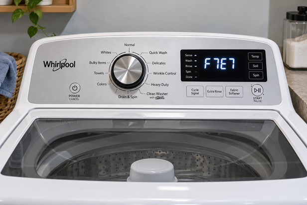
The Whirlpool washer F7E7 error code means the washer’s basket has failed to reach the rotational speed commanded by the main control. Whirlpool identifies this condition as Motor Unable to Reach Target RPM.
Although the error suggests a motor-speed problem, the motor itself isn’t necessarily defective. A binding drive mechanism, slipping belt, weak motor run capacitor, damaged wiring, unbalanced load, or mechanical obstruction can prevent the basket from reaching its required speed.
⚠️ SAFETY FIRST: Always unplug the appliance you're working on from the wall outlet, turn off the breaker, or both, to completely disable power before opening the top console or touching electrical wiring.
The key to diagnosing F7E7 is determining why the basket cannot accelerate properly, rather than immediately replacing the drive motor.
This guide provides model-specific troubleshooting based on Whirlpool service document W11349355A, covering Whirlpool top-load washer models WTW4816FW3 and WTW4850HW3.
The electrical specifications and connector assignments below apply to this documented platform. Other Whirlpool and Maytag washers may use different motor designs, controls, and diagnostic procedures.
What Causes a Whirlpool Washer F7E7 Error Code?
F7E7 is stored when the basket-speed sensing system detects that the washer has not achieved its commanded RPM.
Potential causes include:
Mechanical resistance: Clothing trapped between the basket and outer tub, a binding transmission, or another restriction in the drive mechanism.
Unbalanced load: An unevenly distributed load that prevents normal acceleration.
Defective motor run capacitor: A weak, open, or shorted capacitor can prevent the motor from developing sufficient starting or running torque.
Drive belt or pulley problems: A loose belt, damaged belt, or slipping pulley may prevent the basket from reaching speed.
Drive motor failure: An open winding or weakened motor may cause poor acceleration.
Damaged wiring: Loose terminals or an open connection between the motor, capacitor, and main control.
Main control failure: A control that cannot properly energize the motor windings.
Note that because these failures can produce similar symptoms, diagnosis should proceed from mechanical inspection to electrical testing.
Safety Precautions Before Troubleshooting
Electrical Shock Hazard: Disconnect the washer from electrical power before removing panels, disconnecting connectors, or performing resistance and continuity tests.
Live voltage measurements are for qualified appliance-service professionals using properly rated test equipment.
Never measure resistance on an energized circuit.
Before accessing the underside of the washer, drain the tub and support the appliance securely.
The motor run capacitor can retain an electrical charge after power is disconnected. Follow the manufacturer’s discharge procedure before handling its terminals.
Electronic controls are sensitive to electrostatic discharge. Use appropriate ESD precautions when handling the main control.
1. Confirm the F7E7 Error Code
Before troubleshooting the motor circuit, retrieve the washer’s stored fault codes.
Enter Service Diagnostic Mode
- Place the washer in standby with all status indicators off.
- Rotate the cycle selector counterclockwise one or more clicks to reset the diagnostic entry sequence.
- Within six seconds, rotate the selector:
- Clockwise one click.
- Clockwise one click.
- Clockwise one click.
- Counterclockwise one click.
- Clockwise one click.
- Allow approximately half a second between movements.
Successful entry is indicated by the status LEDs flashing together, except the Lid Locked indicator.
Retrieve Fault History
- Rotate the selector until only the Done LED is illuminated.
- Press Start to enter Fault Code Display Mode.
- Rotate the selector clockwise to review the four most recent stored faults.
- Record all fault codes before clearing them.
Pay particular attention to F7E1, F7E5, and F7E6 if they appear alongside F7E7.
These additional codes may help distinguish a basket-speed sensing problem, shifter failure, or motor-circuit fault.
To clear stored codes, return the selector to the position where the status LEDs flash together, then press and hold Start for three seconds.
2. Check for Mechanical Resistance
Before testing electrical components, determine whether the basket and drive mechanism can rotate freely.
Disconnect power and remove the laundry.
Check for clothing or other material trapped between the inner basket and outer tub.
Rotate the basket by hand and evaluate whether it moves without abnormal binding, scraping, or excessive resistance.
If the basket does not rotate freely, investigate the mechanical restriction before proceeding.
A motor cannot reach its target RPM if the drive system is mechanically overloaded.
Inspect the Drive Belt and Pulleys
With power disconnected and the washer safely supported, inspect the underside of the machine.
Verify that:
- The belt is correctly positioned on both pulleys.
- The belt is not broken, severely worn, or displaced.
- The motor and transmission pulleys are securely attached.
- The splutch mechanism is not binding.
- No foreign object is interfering with drive operation.
Correct any mechanical defects before continuing.
3. Perform TEST #3: Drive System
Whirlpool’s TEST #3 evaluates the motor and related drive components through diagnostic operation.
Run the Heavy Agitation Test
- Enter Service Diagnostic Mode.
- Select Manual Test Mode, indicated by the Spin and Done LEDs.
- Press Start.
- Select Heavy Agitation.
- Close and lock the lid.
- Activate the test.
Allow approximately 15–20 seconds for motor operation.
If the motor agitates normally, the basic motor circuit is functioning during agitation. However, this does not eliminate a weak capacitor, mechanical restriction, or a problem that appears only during spin.
Run the Spin Test
With the tub drained and lid locked, select Low Spin.
Observe whether the basket begins rotating and accelerates normally.
If the motor hums, struggles, stops, or fails to accelerate, continue with the drive-motor diagnostic procedure.
Important: A humming motor does not automatically establish motor failure. A defective run capacitor or mechanical restriction can produce the same symptom.
4. Perform TEST #3b: Drive System – Motor
This procedure checks the motor’s clockwise and counterclockwise circuits, wiring, run capacitor, and control outputs.
For the documented washer platform, the main-control motor connections are:
| Connector | Circuit |
|---|---|
| J2-4 | Motor L1 Common |
| J2-5 | Counterclockwise Motor Winding |
| J2-6 | Clockwise Motor Winding |
These connections are used for both live operating-voltage measurements and power-disconnected winding-resistance tests.
5. Test the Main Control’s Motor Outputs
Qualified Technicians Only — Live 120 VAC Testing
With the main-control connectors seated, use Manual Test Mode to command Gentle Agitation.
Test the Clockwise Motor Circuit
Set the voltmeter to AC volts.
| Meter connection | Test point |
|---|---|
| Black probe | J2-4 — Motor L1 Common |
| Red probe | J2-6 — Clockwise Winding |
| Expected result | Approximately 120 VAC during clockwise motor activation |
If the voltage cycles on correctly, proceed to the counterclockwise circuit.
If the voltage is absent during a valid motor command, investigate the main control and its incoming power supply.
Test the Counterclockwise Motor Circuit
| Meter connection | Test point |
|---|---|
| Black probe | J2-4 — Motor L1 Common |
| Red probe | J2-5 — Counterclockwise Winding |
| Expected result | Approximately 120 VAC during counterclockwise motor activation |
Both motor directions must receive their commanded operating voltage.
If either control output is missing, verify that the washer is correctly executing the diagnostic test before condemning the main control.
Diagnostic significance: If both outputs operate correctly but the motor struggles to accelerate, the motor, run capacitor, harness, and mechanical drive deserve closer investigation.
6. Measure the Drive Motor Windings
Disconnect electrical power.
Remove connector J2 from the main control.
Set the meter to measure low resistance.
Motor Winding Test Points
| Winding | Main-control connector |
|---|---|
| Clockwise | J2-4 to J2-6 |
| Counterclockwise | J2-4 to J2-5 |
Whirlpool specifies different resistance values depending on motor horsepower.
| Motor size | Expected resistance per winding |
|---|---|
| 1/4 HP | 5–9.5 Ω |
| 1/3 HP | 3.5–6 Ω |
Important: Identify the motor configuration before deciding whether a winding is within specification. Whirlpool’s service document identifies machines with a cycle-selector knob and four rotary switches as using the 1/3 HP motor configuration.
Interpret the Results
Both windings within specification: Continue to the motor run capacitor test and related circuit checks.
One or both windings open or outside specification: Inspect the motor connections and wiring harness before replacing the motor.
A resistance measurement made at the control includes the wiring between the control and motor. A damaged wire or terminal can make a good motor appear defective.
7. Verify Motor Wiring and Harness Continuity
Disconnect power and access the motor connections.
Inspect the motor connector and harness for loose terminals, damaged wires, and corrosion.
Check the following connections using an ohmmeter.
| Motor connector | Corresponding circuit |
|---|---|
| Pin 1 | Chassis Ground |
| Pin 2 | Main Control J2-4 |
| Pin 3 | Main Control J2-5 |
| Pin 3 | Run Capacitor Pin 3 |
| Pin 4 | Main Control J2-6 |
| Pin 4 | Run Capacitor Pin 1 |
If continuity is missing, correct the defective connection or replace the lower wiring harness.
If continuity is correct but motor resistance measured at the control was abnormal, isolate and measure the motor windings directly.
Direct Motor Winding Test
| Motor winding | Motor connector pins |
|---|---|
| Clockwise | Pins 4 and 2 |
| Counterclockwise | Pins 3 and 2 |
Use the same horsepower-specific resistance specifications:
- 1/4 HP motor: 5–9.5 Ω
- 1/3 HP motor: 3.5–6 Ω
An out-of-specification winding measured directly at the motor supports motor replacement.
8. Test the Motor Run Capacitor
A failing motor run capacitor is an important consideration when diagnosing the Whirlpool washer F7E7 error code.
A capacitor that has lost capacitance may allow the motor to run under some conditions while preventing it from developing enough torque to accelerate the basket.
Typical symptoms include:
- Motor humming without starting.
- Slow basket acceleration.
- Intermittent spin failure.
- Motor stopping before reaching the commanded speed.
Capacitor Inspection and Testing
Disconnect power and follow the manufacturer’s capacitor discharge procedure.
Inspect the capacitor and its terminals for visible damage or loose connections.
With the capacitor isolated from the circuit, use an appropriate capacitance meter to measure its actual capacitance.
Compare the measurement with the rating printed on the capacitor and its specified tolerance.
Do not assume a capacitor is good simply because it is not shorted or open. A capacitor can lose capacitance and still produce an apparent charging response on an ohmmeter.
If the capacitor is outside its rated tolerance, replace it with the correct model-specific component. A sound alone does not confirm capacitor failure; use the isolated component measurement and the actual rating and tolerance.
If the capacitor tests correctly, continue investigating the motor and control circuits.
9. Verify Tachometer Feedback
The main control relies on speed information to determine whether the basket is reaching its commanded RPM.
If motor operation and mechanical drive components appear satisfactory, verify that the control receives basket-speed information.
Enter Tachometer Verification Mode
- Enter Service Diagnostic Mode.
- Rotate the selector until Wash and Done are illuminated.
- Press Start.
- Slowly rotate the basket by hand.
The following status LEDs should illuminate individually in a repeating sequence:
Done → Spin → Rinse → Wash
The sequence indicates that the control is receiving tachometer feedback as the basket rotates.
If the indicators do not respond correctly, investigate the shifter’s optical speed sensor and associated wiring using the model-specific shifter diagnostic procedure.
A speed-feedback failure can interfere with accurate motor-speed detection even when the motor itself operates.
10. Determine Which Component Needs Replacement
Use the results of the preceding tests to identify the failed component.
| Diagnostic finding | Recommended action |
|---|---|
| Basket or drive mechanism binds | Correct mechanical obstruction or failed drive component |
| Belt damaged or displaced | Repair belt or pulley problem |
| Motor winding out of specification directly at motor | Replace drive motor |
| Harness continuity missing | Repair connection or replace harness |
| Run capacitor outside its rated tolerance | Replace capacitor |
| Motor control output missing during valid test | Diagnose main control |
| Tachometer feedback missing | Diagnose optical sensor and related wiring |
Avoid replacing the motor, capacitor, and main control as a package without supporting diagnostic evidence.
Related Drive-System Error Codes
The F7E7 error indicates that the washer cannot reach its commanded motor speed. However, similar symptoms can occur with other drive-system faults.
If the washer also reports an F7E6 motor circuit fault, investigate the motor circuit and its associated wiring.
If an F7E5 shifter fault is present, follow the actuator and position-sensing troubleshooting procedures to determine whether the shift mechanism is operating correctly.
11. Calibrate and Verify the Repair
After repairing the drive system, perform calibration when required by the washer’s configuration and the component replaced.
Whirlpool document W11349355A specifies calibration for applicable machines without manual level selection after replacement of certain components, including the motor, capacitor, and main control.
Run Calibration Mode
- Ensure the basket is empty.
- Close the lid.
- Enter Service Diagnostic Mode.
- Rotate the selector until only Rinse is illuminated.
- Press Start.
The calibration cycle normally takes approximately 2–4 minutes, although some configurations may require longer.
Do not interrupt the procedure.
Run Automatic Diagnostic Test
After calibration, enter Automatic Test Mode by selecting the Spin LED and pressing Start.
The washer will operate its major components through a programmed test sequence.
At completion:
- All status LEDs illuminate for five seconds if the test passes.
- All status LEDs flash for five seconds if the test fails.
If the test fails, retrieve the stored fault codes and continue diagnosis.
Conclusion: Fixing the Whirlpool Washer F7E7 Error Code
The Whirlpool washer F7E7 error code indicates that the basket has failed to reach its target rotational speed. Although a defective drive motor can cause this condition, it is only one of several possibilities.
Mechanical resistance, a worn drive belt, weak run capacitor, damaged motor wiring, and inaccurate speed feedback can all prevent normal acceleration.
A dependable repair begins by identifying whether the problem is mechanical or electrical. From there, testing the motor windings, control outputs, run capacitor, wiring harness, and tachometer feedback provides the evidence needed to identify the actual failure.
For Whirlpool models WTW4816FW3 and WTW4850HW3, the connector locations and electrical specifications in this guide provide a model-specific starting point for accurate troubleshooting.
The bottom line: Don’t replace a motor simply because the washer stores F7E7. Determine why the basket cannot reach its commanded speed, confirm the defective component through testing, and verify the repair with calibration and an automatic diagnostic cycle.
That is how you turn an F7E7 error code into a reliable diagnosis rather than an expensive guessing game. Thanks for stopping by!
OEM reference and applicability
Technical basis: Whirlpool W11349355A, fault chart pages 6–7; TEST #3/#3a/#3b pages 13–16; modes pages 2–5. AFC’s library associates this sheet with WTW4816FW3 and WTW4850HW3. Match the technical sheet supplied with the complete model number and revision before using these procedures. A similar control panel does not establish applicability. The OEM sheet is intended for service technicians.
Document identifier: W11349355A. Use the appliance’s supplied sheet or obtain the applicable service document from Whirlpool. Exact electrical test conditions and component access are part of the procedure, not optional details.