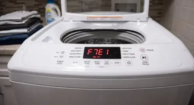
On the W11349355A configuration, F7E1 is a basket-speed fault: the control cannot determine basket speed or sees speed changing too quickly. This is different from proving the optical sensor has failed. Mechanical restrictions, wiring, motor/capacitor problems, and the shifter system all need consideration.
Applies to: the Whirlpool top-load washer configuration documented in service sheet W11349355A. It does not supply universal instructions for all Whirlpool, Maytag, Amana, Kenmore, Cabrio, Bravos, or front-load washers. Check the full model number and its technical sheet first.
⚠️ SAFETY FIRST: Always unplug the appliance you're working on from the wall outlet, turn off the breaker, or both, to completely disable power before opening the top console or touching electrical wiring.
Make the situation safe
Disconnect power before opening panels, disconnecting connectors, or checking resistance or continuity. Never bypass the lid interlock or reach into a moving basket. Live electrical measurements belong to a qualified appliance-service professional following the complete OEM procedure. Drain the tub using the model’s approved method before underside access, and support the machine securely. Do not work beneath an unsupported tilted washer.
Retrieve the stored fault before replacing parts
On the matching W11349355A configuration, use the following sequence with the washer fully assembled. Stop if there is uncontrolled filling, leakage near electrical equipment, severe mechanical movement, or a burning smell.
- Place the washer in standby: plugged in, with all indicators off. After initial power is applied, wait 10 seconds.
- Turn the cycle selector counterclockwise one or more clicks to reset the entry sequence. This does not erase stored faults.
- Within six seconds, turn clockwise one click three times, then counterclockwise one click, then clockwise one click. Allow about half a second between movements.
- Successful entry makes the status LEDs flash together, except Lid Locked. Turn the selector until only Done is illuminated, then press Start.
- Turn clockwise to review the four most recent stored faults. Record them before clearing anything.
If pump-out is active, diagnostics are unavailable until it completes. OEM W11349355A describes holding Start for three seconds to cancel pump-out before retrieving faults. Removing power pauses pump-out; it does not reset that condition. Use this step only when the washer can be operated safely.
Inspect the mechanical drive before testing electronics
With power disconnected, check for abnormal basket binding, trapped clothing, a displaced belt, and loose pulleys. Drain first and use securely supported, model-approved access for underside inspection. A damaged part needs inspection; a noise or oily belt alone does not identify the failed assembly.
Technician diagnosis: TEST #3 and TEST #3a
The following checks require the matching OEM sheet and safe access. Isolate power before connecting or disconnecting test leads or harnesses; resistance tests use the disconnected harness or isolated component specified by the OEM. Follow all live-measurement precautions in the sheet.
The documented diagnostic route evaluates agitation and spin, shifter position, optical-sensor supply, and harness continuity. The lid must be closed and locked for agitation/spin operation. On the matching source, shifter motor resistance is 2–3.5 kΩ at J2-1/J2-2 on the disconnected harness. That motor reading does not prove the optical sensor works.
The position signal is measured at J12-3 relative to J12-4: 0 VDC in Agitate and +5 VDC in Spin. Optical-sensor supply is +12 VDC at J12-1 relative to J12-4. These powered checks are for qualified technicians following the complete source procedure.
Tachometer Verification Mode uses Wash and Done, then Start. Slowly turning the basket by hand produces individual status-LED responses. Use the OEM sequence and wiring checks to distinguish loss of supply, harness failure, and absent feedback. Do not substitute unverified actuator-terminal pins from another guide.
Check the actual capacitor rating
A motor-run capacitor may retain charge after disconnection. Follow the manufacturer’s discharge and isolation procedure. If measuring capacitance, compare the result with the fitted capacitor’s marked rating and tolerance and use the correct replacement specification. A universal 50 µF rating or 45 µF rejection threshold is not supported for every washer. A growling or humming sound alone is not a capacitor test.
Select parts only after confirmation
Use the complete model number, engineering revision, and confirmed failed component to select a replacement. A code alone does not prove that the named component is defective. Generic product photographs and a similar-looking part do not establish fitment.
Verify the repair
Reassemble all panels and reconnect every disturbed connection before normal operation. Correct any leak or mechanical hazard before running a test. On this documented configuration, select Automatic Test Mode from diagnostics with the Spin LED, then press Start; the lid must be closed and locked. The programmed test uses water. A pass illuminates the status LEDs for five seconds; a failure flashes them for five seconds. Retrieve any faults after a failed test and continue diagnosis.
Calibration and fault-history clearing are different operations. W11349355A limits Calibration Mode to models without level selection, and lists replacement of the main control, basket, drive assembly, suspension, motor, and capacitor as calibration triggers. Follow the relevant component-test procedure as well. Where required, use an empty basket, lid down, select Rinse in diagnostics, and press Start. Allow approximately two to four minutes without interruption; some configurations take longer.
To clear history after recording it, enter Fault Code Display Mode, turn to the flashing-status-LED position, and hold Start for three seconds. The sheet also removes a fault after five consecutive wash cycles without recurrence. Clearing history is not a repair or a calibration step.
OEM reference and applicability
Technical basis: Whirlpool W11349355A, F7E1 fault chart page 7; drive/shifter tests pages 13–14; capacitor procedure pages 15–16; modes pages 2–5. AFC’s library associates this sheet with WTW4816FW3 and WTW4850HW3. Match the technical sheet supplied with the complete model number and revision before using these procedures. A similar control panel does not establish applicability. The OEM sheet is intended for service technicians.
Document identifier: W11349355A. Use the appliance’s supplied sheet or obtain the applicable service document from Whirlpool. Exact electrical test conditions and component access are part of the procedure, not optional details.