
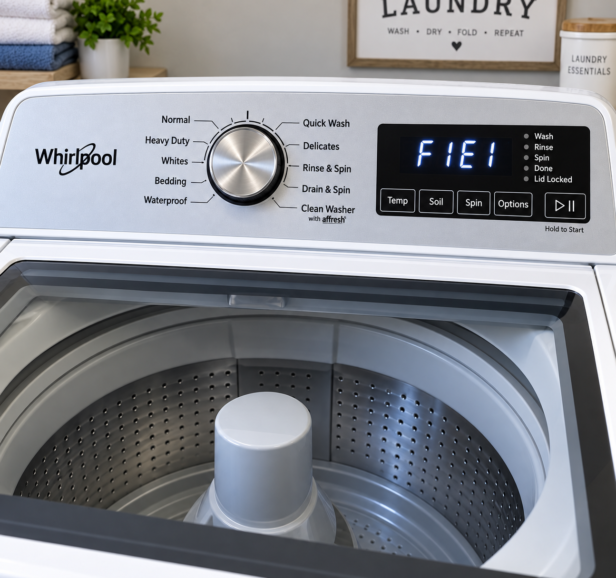
An F1E1 error code indicates a Main Control (ACU) Fault on Whirlpool and Maytag 4.7 / 5.3 cu. ft. top-load washers. This fault signifies an internal microprocessor failure or a loss of DC logic supply voltage on the control board.
A diagnostic light (LED) is located directly on the main control board surface to assist in visual diagnosis:
⚠️ SAFETY FIRST: Always unplug the appliance you're working on from the wall outlet, turn off the breaker, or both, to completely disable power before opening the top console or touching electrical wiring.
- LED Flashing: The control board detects correct incoming line voltage and the microprocessor is operating.
- LED ON or OFF: Control board malfunction. Perform Test #1: Main Control (ACU).
Safety & Electrostatic Discharge (ESD) Precautions
- Electrical Shock Hazard: Disconnect main power before removing access panels, handling internal wiring, or checking electrical continuity.
- Live Voltage Testing Safety: Live voltage measurements must only be performed by authorized service professionals. Ensure controls are OFF before energizing, maintain a clear workspace, keep bystanders away, use proper testing equipment, and disconnect power immediately after taking readings.
- Terminal & Header Care: Avoid inserting large-diameter test probes into female harness connectors, as this deforms female contact barbs. Never bridge or short adjacent pins on circuit board headers.
- ESD Protection: Static discharges as low as 10 volts can destroy or weaken electronic controls. Touch an unpainted metal ground point before handling controls, or wear an anti-static wrist strap connected to ground. Touch anti-static packaging to ground before opening, and hold circuit boards strictly by their plastic housing edges.
1. Confirm the Fault and Check the Basics
- Verify wall outlet power and inspect for a blown household fuse or tripped breaker.
- To view stored fault codes using Service Mode:
- Start with the washer plugged in, in standby, with all indicators off.
- Choose any 3 buttons other than POWER.
- Press and release them in sequence (1-2-3, 1-2-3, 1-2-3), completing all 9 presses within 8 seconds.
- When the technician message appears on the LCD screen, navigate to Fault History using the Left/Right keys and press Select/Enter (Key 2).
- If entry fails because buttons do not respond or change functions, replace the User Interface (UI). If no indicators turn on after selecting a cycle, proceed directly to Step 2.
- With power disconnected, inspect all wiring harnesses and connectors between the main control and console for loose plugs, unseated terminals, broken wires, or corrosion.
2. Verify Incoming Power at the Main Control
- Unplug the washer or disconnect power.
- Access the main control board inside the console.
- Confirm that all harness connectors are inserted all the way into the main control.
- Set your multimeter to AC Volts. Attach probes to connector J1:
- Black probe: J1-1 (Neutral)
- Red probe: J1-2 (Line)
- Restore power and check the reading:
- 120 VAC Present: Continue to Step 3.
- 120 VAC Absent: Disconnect power and check the AC power cord for electrical continuity.
3. Check the Main Control’s Diagnostic Light
With incoming 120 VAC verified at connector J1, inspect the green Diagnostic LED located directly on the main control board:
- Flashing: The +5 VDC supply is present and the microprocessor is operating. Proceed to Step 5 (Test the console and its wire harness).
- Steadily ON: The +5 VDC supply is present, but this result identifies a microprocessor failure. Skip to main-control replacement in Step 6.
- OFF: The +5 VDC supply is missing or there is a microprocessor failure. Continue to Step 4 for the console disconnection test specific to your washer’s drive type.
4. Check the DC Power Supply at the Console Header
Disconnect power before unplugging connectors or touching probes to board headers. Measure voltage inside the board header; do not measure the disconnected harness plug. Do not short adjacent pins together.
4A. Maytag Belt-Drive Models
- Disconnect power and remove connector J5 from the main control.
- Restore power and set meter to DC Volts.
- Measure inside the J5 header on the board:
- Black probe: J5-4 (Circuit Ground)
- Red probe: J5-1 (+12 VDC)
- Verdict: If +12 VDC is missing, or if +12 VDC is present but the Diagnostic LED is not flashing, replace the main control board.
4B. Whirlpool Belt-Drive Models
- Disconnect power and remove connector J11 from the main control.
- Restore power and set meter to DC Volts.
- Measure inside the J11 header on the board:
- Black probe: J11-4 (Circuit Ground)
- Red probe: J11-1 (+12 VDC)
- Verdict: If +12 VDC is missing, or if +12 VDC is present but the Diagnostic LED is not flashing, replace the main control board.
4C. Whirlpool & Maytag Direct-Drive Models
- Disconnect power and remove connector J14 from the main control.
- Restore power and recheck the Diagnostic LED:
- If LED now flashes: The console UI was pulling down the DC supply. Proceed to Step 5 (HMI Test).
- If LED still does not flash: Disconnect power before attaching probes. Set meter to DC Volts.
- Measure inside the J14 header on the board:
- Black probe: J14-4 (Circuit Ground)
- Red probe: J14-1 (+12.7 VDC)
- Restore power.
- Verdict: If +12.7 VDC is missing, or if +12.7 VDC is present but the LED is not flashing, replace the main control board.
5. Test the Console and Its Wire Harness
When directed to test the Human-Machine Interface (HMI), enter Service Mode -> Service Diagnostics -> HMI Test:
- Key Test: Test button responses per screen prompts (hold any key 3 seconds to exit).
- LED Test: Verify LEDs toggle ON, 50 percent, and OFF.
- Display Test: Confirm repeating color and pattern sequences.
- Audio Test: Verify speaker tone output sequences.
- Encoder Test (where fitted): Rotate cycle knob through both clockwise and counter-clockwise positions.
Console Harness Continuity Checks
If functional tests fail, disconnect power. Inspect harness connections and ribbon cables at both ends, then test wire continuity along each specified wire:
| Drive Configuration | Main Control (ACU) Terminal | Wire Color | Console HMI Terminal |
|---|---|---|---|
| Maytag Belt Drive | J5-1 J5-3 J5-4 | Red Yellow Black | J1-1 J1-3 J1-4 |
| Whirlpool Belt Drive | J11-1 J11-3 J11-4 | Red Yellow Black | J1-1 J1-3 J1-4 |
| Direct Drive (Whirlpool & Maytag) | J14-1 J14-3 J14-4 | Red Yellow Black | J1-1 J1-3 J1-4 |
(Important: HMI J1 is the terminal on the console assembly; it is not the main control J1 used for 120 VAC power input testing). The manual specifies continuity for these checks without providing a numerical ohm limit.
- Continuity Fails: Replace the console wire harness.
- Continuity Passes: Replace the User Interface / HMI assembly.
6. Replace the Component Confirmed by Testing
Accessing the Console
- Unplug washer and turn off water supply.
- Remove two rear console screws (1/4-inch hex-head / T20 TORX).
- Raise the lid. While pushing back and up on the console, slide a thin plastic putty knife between the console and top panel to depress the console clip.
- Close the lid and tilt the console forward for access.
Removing a Failed Main Control (ACU)
- Disconnect pressure hose from the ACU.
- Disconnect all ACU wire connectors.
- Use a 1/4-inch nut driver to remove the hex-head screw securing the ACU to the top panel.
- Slide the ACU to the left and lift it out.
- Here’s a typical representation of a common main control.
Removing a Failed User Interface (UI)
- Depress tab and lift to disconnect the three-wire UI harness from the ACU.
- Remove the eight 1/4-inch hex-head screws securing the UI to the console.
- Gently depress the four plastic mounting clips with a flat-blade screwdriver.
- Lift the console shell away to access the UI.
- Reassembly Note: Hand-tighten the eight screws until snug. Using a power driver can strip screw holes and stress the capacitive-touch interface.
7. Calibrate After Control Replacement and Verify the Repair
After replacing the main control board, enter Service Mode and select Factory Diagnostics -> DLMS Calibration Cycle. (Note: The separate Factory Calibration Cycle option is for factory testing only).
DLMS Calibration Rules
- Keep the lid down.
- Leave the basket empty of both water and clothing.
- Allow approximately 2 to 4 minutes for cycle execution.
- Do NOT interrupt calibration, disturb the washer, or remove power; otherwise, calibration must be repeated.
- Completion: The cycle finishes when the lid unlocks and the display returns to the service diagnostic screen shown before calibration began.
Final Repair Verification
Complete the automated Diagnostic Cycle required under Service Diagnostics. Keep the lid closed for the entire cycle; opening it cancels the test. Faults encountered during the cycle are recorded in Fault History, even if they do not appear on the display.